4 Bit Adder Circuit
11+ 4 bit adder circuit diagram Let's learn computing: 4 bit adder circuit Adder cmos soi
Circuit diagram of a one-bit full adder using the proposed technique in
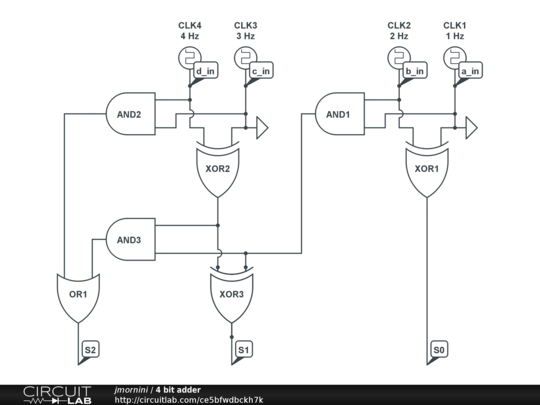
4 bit adder Bit circuitlab adder circuit description Adder bcd
Circuit adder bit diagram logic computing learn let
Adder circuit diagram schematic bit works figureFull-adder circuit, the schematic diagram and how it works – deeptronic Download 4 bit adder circuit stick and logic diagramAdder alu nor nand.
11+ 4 bit adder circuit diagram5 logic circuits Adder bit circuits four figure logic x64 sonoma cs bob eduAdder bit using circuit adders half four implementation watson circuits single just box into figure latech edu outputs.
![11+ 4 Bit Adder Circuit Diagram | Robhosking Diagram](https://i2.wp.com/d2vlcm61l7u1fs.cloudfront.net/media/253/253477c4-ac8d-4971-8cb5-c9289fcbdbfb/phpgdrbul.png)
Circuit diagram of a one-bit full adder using the proposed technique in
Let's learn computing: 4 bit adder circuitAdder bit circuit 4-bit addition operation circuit using half adder and full adderCircuit adder bit half using diagram operation addition seekic basic additive four use ic.
.
![5 Logic Circuits](https://i2.wp.com/bob.cs.sonoma.edu/IntroCompOrg-x64/book_figs/adder4.png)
![4-bit addition operation circuit using half adder and full adder](https://i2.wp.com/www.seekic.com/uploadfile/ic-circuit/20111252213682.jpg)
![Watson](https://i2.wp.com/watson.latech.edu/WatsonRebootTest/Images/fig12-fourbitadder.png)
![Full-Adder Circuit, The Schematic Diagram and How It Works – Deeptronic](https://i2.wp.com/www.deeptronic.com/wp-content/uploads/2019/09/4-bit-adder-circuit.png)
![Download 4 bit adder circuit stick and logic diagram - Educative Site](https://i2.wp.com/educativesite.com/wp-content/uploads/2019/08/4-bit-adder.png)
![Circuit diagram of a one-bit full adder using the proposed technique in](https://i2.wp.com/www.researchgate.net/publication/276493953/figure/download/fig1/AS:612883918516224@1523134321890/Circuit-diagram-of-a-one-bit-full-adder-using-the-proposed-technique-in-SOI-CMOS.png)
![Let's Learn Computing: 4 bit Adder Circuit](https://4.bp.blogspot.com/-cgrXCstw9dI/UUnxC4ZoZwI/AAAAAAAAAUE/J5pv83rANvo/s1600/Untitled.png)
![Let's Learn Computing: 4 bit Adder Circuit](https://4.bp.blogspot.com/-cgrXCstw9dI/UUnxC4ZoZwI/AAAAAAAAAUE/J5pv83rANvo/w1200-h630-p-k-no-nu/Untitled.png)
![11+ 4 Bit Adder Circuit Diagram | Robhosking Diagram](https://i2.wp.com/media.cheggcdn.com/media/69d/69d16419-1d4d-46a9-9669-f907cf2efd23/php4BG2gJ.png)